Transfer from W4FAO to KM4TTS

Acting at the request of W4FAO he’s requested to transfer his coordination’s to KM4TTS.

145.1100|144.51|16K0F3E|NULL|123.0|123.0|NULL||NULL||0|||||1134|1|KM4TTS|Andy Rudd, KM4TTS|Madison|2020-07-06|2020-01-04|30.47|-83.42|41.45|NULL|NULL|97|20.000|35|88|NULL|NULL|1|https://plots.fasma.org/144/145.1100_KM4TTS_Madison_1134.kmz|0|0|0|0||0||0|0|0|N|0||0
145.1900|144.59|16K0F3E|NULL|123.0|123.0|NULL||NULL||0|||||1031|1|KM4TTS|Andy Rudd, KM4TTS|Lee|2020-10-02|2020-01-04|30.42|-83.30|41.45|NULL|NULL|65|20.000|26|75|NULL|NULL|1|https://plots.fasma.org/144/145.1900_KM4TTS_Lee_1031.kmz|0|0|0|0||0||0|0|0|N|0||0
442.0000|447|16K0F3E|NULL|123.0|123.0|NULL||NULL||0|||||1101|1|KM4TTS|Andy Rudd, KM4TTS|Lee|2020-12-07|2020-01-04|30.42|-83.30|41.45|NULL|NULL|62|25.000|28|70|NULL|NULL|1|https://plots.fasma.org/440/442.0000_KM4TTS_Lee_1101.kmz|0|0|0|0||0||0|0|0|Y|0||0
444.3000|449.3|16K0F3E|8K10F1E|94.8|94.8|NULL||NULL||0|||293|293|1035|1|KM4TTS|Andy Rudd, KM4TTS|Madison|2020-10-04|2020-01-04|30.48|-83.45|60.96|NULL|NULL|90|25.000|34|83|NULL|NULL|1|https://plots.fasma.org/440/444.3000_KM4TTS_Madison_1035.kmz|0|0|0|0||0||0|0|0|N|0||0

444.3000 KM4TTS Madison

442.0000 KM4TTS Lee

145.1900 KM4TTS Lee

145.1100 KM4TTS Madison

147.2100 SERA Opp, AL

Adjacent coordination granted by SERA.

https://plots.fasma.org/144/147.2100_SERA_Opp-AL_1489.kmz

147.2100|147.8100|16K0F3E|NULL|NULL|NULL|NULL|NULL|NULL|NULL|NULL|NULL|NULL|NULL|NULL|1489|1|SERA|NULL|Opp-AL|NULL|2020-01-03|31.25|-86.21|30.48|NULL|NULL|89|15.000|32|97|28|NULL|1|https://plots.fasma.org/144/147.2100_SERA_Opp-AL_1489.kmz|NULL|NULL|NULL|NULL|NULL|NULL|NULL|NULL|NULL|NULL|NULL|NULL|NULL|NULL
147.2100 SERA Opp, AL

443.8125 W4VCO Bartow DMR Coordination Granted

443.8125 W4VCO Bartow

This DMR repeater coordination is granted.

443.8125|448.8125|7K60FXE|NULL|NULL|NULL|1|1|1|2|0|NULL|NULL|NULL|NULL|1485|1|W4VCO|Julian A. Homan, W4VCO|Bartow|2020-01-03|2020-01-03|27.75|-81.89|126.00|LTOWER|455-5N|212|12.500|50|97|NULL|NULL|1|https://plots.fasma.org/440/443.8125_W4VCO_Bartow_1485.kmz|NULL|NULL|NULL|NULL|NULL|NULL|NULL|NULL|NULL|NULL|NULL|0|NULL|1
443.8125 W4VCO Bartow

Modeling Repeaters in North Florida

With the recent success of modeling all coordinated repeaters in the state, we’ve found some issues with the existing data. Issues including, coordinates being way off, powers wrong, ERP wrong and so forht. Then a major problem in northern Florida was discovered, models were ignoring the digital elevation model (DEM) when coverage was being plotted.

FASMA uses an implementation of Longely-Rice or the Irregular Terrain Model which takes into account the elevations of terrain and loss due to signals scattering and absorbed by terrain. Essentially when this data is missing it’s assumed as sea-level and the model generated is very smooth, and concentric about the transmitter. Such a model is quite far off from reality, and can over or under state the coverage (understanding is possible as we assume the antenna height above ground is now at sea level, not the actual height).

The DEM data used was provided by the Shuttle Radar Topography Mission (SRTM) which mapped the surface of the earth at resolutions not available before. The earth was scanned and elevation was averaged over 1 and 3 arc-seconds (30m and 90m). FASMA uses the 90m data as there is little gained, other than a much longer processing time, using the 30m average for non-microwave work. The USGS has several different versions of this data released, but by the most common is 2.1, which has the ability to be directly downloaded from a web-server at the USGS.

This brings us to the issue with north Florida. An example for this is the below repeater model:

NF4CQ Lake City with bad DEM data

The solid color area here indicates the model has no variation in elevation for most of it. This appears to be a rhombus shaped void centered just south of Lake City and obscuring most of North Florida. The underlying SRTM data was checked and found to possess the same void.

This discovery prompted much research into the SRTM data, and the 30m data was found to have the same issue. In the image below it can be seen of a massive gap across north Florida. Further research found this to be a product of “voids” or gaps in the SRTM radar. Typically this effects areas of deep canyons and high variation where the radar cannot see due to the angle of the shuttle to the surface of the earth. These areas of uncertainty are removed and set to negative elevation.

Black is Sea-Level, note the gap from Ocala to the State Line

USGS has newer versions of data available, known as Version 3 and includes what’s know as void fill, however it is not available for direct download. An account is required and one must point-and-click through the USGS map server interface for it. This precludes downloading automatically, as the number of 3 x 3 tiles required for US coverage is impractical to download by hand. The download is also in a different format than the HGT SRTM standard, and would need to be converted. As luck would have it, there is a web download of the SRTMv3 data as the HGT files, but it requires a user/password once registered with USGS. Using this password and some shell scripting, the entire world was able to be downloaded as SRTMv3 HGT zip files. All 14280 of them.

As the FASMA modeling program is based on SPLAT!, a conversion is required to SDF from HGT of the data. The SDF files are much larger with the entire wold of SDF files taking ~77 GiBytes of space. SPLAT! does support bzip2 compressed SDF, and a multi-threaded version of bzip2, pbzip2 was uses to compress the files in short order on a 24 core server. This compressed down to a more reasonable 10 GB.

After remodeling a number of repeaters in North Florida, it was found some tiles of DEM data looked to be corrupted, with some areas below sea-level and others with “noise” data in them. Comparisons were made with the source SRTM files and found to be perfect. Data looked good and gdal_translate was used to make PNG’s of the terrain, confirming the SRTMv3 was not the source of the issue.


After much trial and error to locate the bug, it was discovered uncompressed SDF files worked fine. Further when compressed again with bzip2, the resulting sdf.bz2 file rendered as expected. This was quickly confirmed as the library in SPLAT! not being able to decompress files compressed with pbzip2 perfectly. A script was made to unbzip and then bzip2 all sdf files in place. The results below show it was a simple fix. The ultimate issue will be submitted as a bug report.

The Lake City 444.9000 NF4CQ revised plots using the SRTMv3 models are below. Note due to the void “fill” it’s not a perfect and we have some discrepancies in the elevation corrections and the valid SRTM data. This is not perfect but it’s much better than assuming sea-level, especially for elevations in North Florida where 30-40m ASL is normal.

References:


http://srtm.fasma.org/ – FASMA has made it’s collection of SRTMv3 HGT and SDF data for the wold available for direct download.

https://e4ftl01.cr.usgs.gov/MEASURES/SRTMGL3S.003/2000.02.11/ – USGS SRTMv3 source, password required.

Coordinated Repeater Models

Recently we’ve completed the modeling of all coordinated repeaters in Florida. This was scripted and database driven modeling. Right now the individual KMZ files are available at https://plots.fasma.org under the various bands. Each KMZ file has the service, interference and point of repeater, along with channel size and modulation type.

Most repeater owners/operators/trustees will look at the service contour which is in blue. This shows an area where at 1.83m (6′) above the ground, there is a 50% chance that location will have a signal, 50% of the time greater or equal to the service contour. This is typically the mobile service area of a repeater and designated (50, 50).

The green interference contour is modeled to show 50% of locations 10% of the time (50,10) where a signal will be 18 dB below the service contour. This de-rating to 10% makes the chances of receiving a signal much smaller and thus the interference contour is larger. No other co-channel users interference contour should overlap the service contour of any other repeater. This ensures a repeater in it’s protected service contour has a signal at least 18 dB greater than any co-channel repeaters.

In some cases there are adjacent contours, and these are used much like the interference contour. No adjacent contour should overlap another service contour. These are used on 144-146 and 146-148 MHz and for narrowband in 222-225 MHz.

The eventual goal is to have this database driven in real time. This is being worked on and we hope to have a much better interface shortly.

Comparison of Radio Propagation Modeling Software

Recently discussions regarding the use of various software in the study of coordination modeling have happened.  All claim to implement the same models along with their own variations or empirical derived models.  The model we are most interested in is known as Longley–Rice, or the irregular terrain model (ITM).  This model is optimized to cover 20 to 20,000 MHz for predicting signal strength over real terrain when used with a digital elevation model (DEM).

The ITM model in area propagation mode essentially breaks up the underlying map into tiles of a given resolution, and taking account the DEM heights, computes the signal level in a tile and then onto the adjacent tiles and so on using the now attenuated signals from the source area.  The original code was written in FORTRAN, converted to C++ and has been re-implemented a number of times to speed it up, improve it and add a given vendors “secret sauce”.  The original docs and code may be found on the ITS website.  Keeping in mind the ITM model was used to layout FM and most importantly the VHF/UHF Television spectrum in the 1960’s it’s proven to be a reliable model.  Land Mobile radio has adopted the same basic concepts in needing to predict interference between co and adjacent channel users, albeit with different criteria than TV broadcasters.

As amateurs push to coordinate frequency use in their spectrum, it’s imperative we understand our tools and what software we may use to predict coverage.  This is more important we have repeatable standards which anyone can model and check to keep our coordination bodies honest as well.  FASMA has standardized on SignalServer which is a multithreaded version of SPLAT!, both implement the C++ version of the ITM model.  Also common in amateur circles is the use of RadioMobile, a non-free application for windows operating systems.

Commercially there are many packages used for radio modeling, and two of the most popular are ComStudy and Pathloss.  ComStudy is the de-facto standard used by the LMR coordinators approved by the FCC and implements it’s own proprietary version of the ITM model and ships with an additional land cover database.  Pathloss 5 is mostly known in the Part 101 and microwave Point to Point (PtP) modeling space, but has an ITM mode, and unlike most software, describes the algorithm implemented in great detail.  As Pathloss doesn’t provide source code, we cannot be sure how faithfully they have implemented the ITM model.

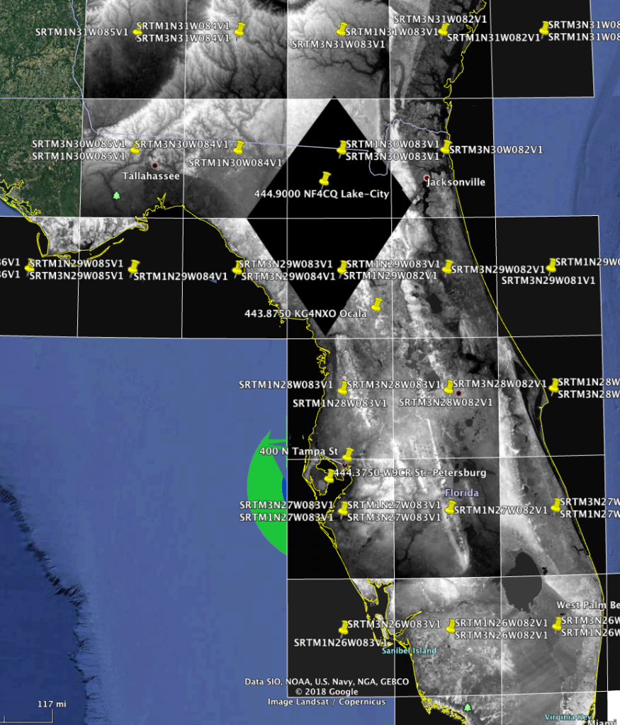
The DEM model data used is the 3 arc second resolution data from the Shuttle Radar Topography Mission (SRTM).  This is a digital model of the earth’s elevation in 90×90 meter tiles as a height.  This works well for most areas, but there is higher resolution data 1 arc second and even 1/3rd arc-second available for certain areas of the earth.  Ultra-high resolution DEM data has national defense implications, and is generally not available.  The SRTM data typically includes the tops of trees in forests, which can present a problem if a tower is in a forest.  We can say the height above ground is 100 meters, but if the adjacent trees are 20 meters average height, the model AGL should adjusted to 80m (100-20 tree height), or we will be modeling the system 20m too high.  This same phenomena can present in dense cities as an urban forest area.


Modeling Criteria

In comparison we have modeled a test repeater with an omni directional antenna as follows:
<font=monospace>

Latitude:        42.33
Longitude:      -87.91
Frequency:      446 MHz
Antenna Height Above Ground: 97.5 meters
ERP:            707 watts
Signal Criteria: 39 dBuV/m (dBu)
Reliability and confidence criteria - (50, 50)

Signal Server

SignalServer was invoked with the following command:

./signal-server-base.sh -lat 42.328889 -lon -87.912500 -txh 97.54 -f 445 -erp 707 -rt 39 -conf 50 -o blueblue | ./genkmz.sh

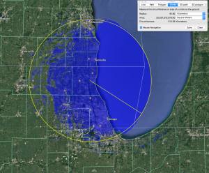
This produced the plot below with a radius (based over the water) of 62km.

The reason for basing the plot over the water for radius is it should be the same height and signal strength in all models, as there is nothing there.

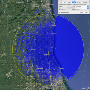
This plot took about 150 seconds on a quad core computer.

The Keyhole Markup Language file is here, and a version of the same plot, but red is here.  The red color version is useful for comparing and contrasting with the other results in the various shades of blue.

RadioMobile

RadioMobile is interesting as its non-Free Software, but doesn’t appear to have a commercial use keeping it from being Free Software.  Due to the GUI, it’s popular with a number of amateurs.  The configuration for generating plots is quit complex and poorly documented to get a 1:1 ITM model from it.  RadioMobile is not multi-threaded, in fact the entire GUI locks up while rendering, however a render is completed on a Dell D830 (a laptop circa 2006) in about 60 seconds.  From this we must assume some “speedups” or shortcuts in the code are taken when compared to the ITM reference code.

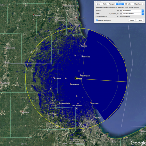
We followed the FASMA reference guide on modeling in RadioMobile for this plot.

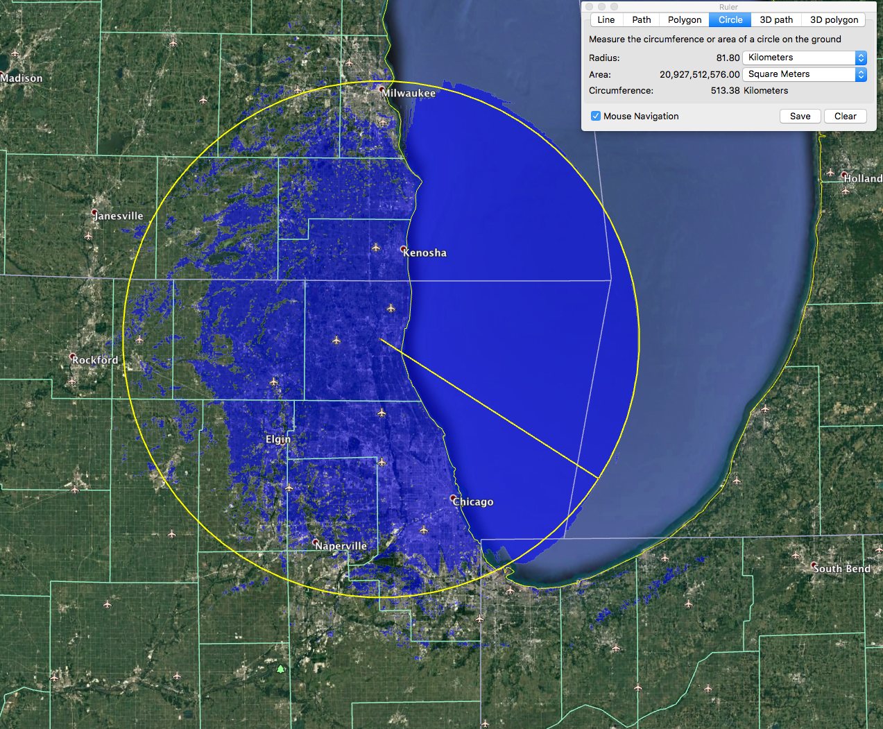
This modeled with an 82km radius over water, and seemed to have greatly overstated coverage compared to the other models.


Pathloss 5.1

Pathloss has no easy way to export the configuration for a model.  We had this modeled by a trained professional user of the software.  Pathloss in area mode is exceptional slow, there below took about 12 hours to render.  We found no multi-threading taking place, and like RadioMobile the GUI locked up during this. Based on this, we can assume the code very close to the ITM reference.

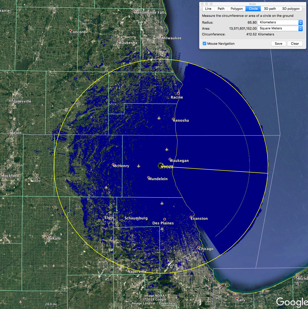
The radius here was 65km and compared very closely with the SignalServer model.

The Keyhole Markup file of this is here.

ComStudy 2.2

ComStudy was run by an experienced engineer who has worked LMR across the VHF and UHF business spectrum.  Again there is no easy open way to export the study inputs for ComStudy, but the below files were modeled.  We didn’t have exact measurements of time for the generation of the below plots.

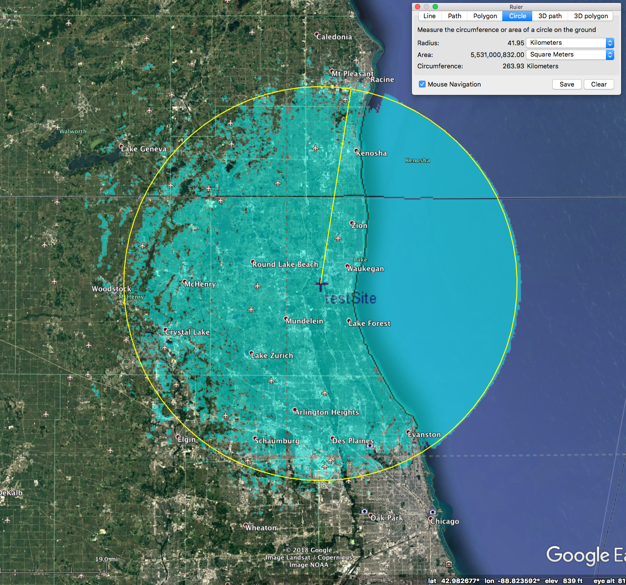
This is a 42km radius and has the smallest area of any model we studied.  The Keyhole Markup file is here.

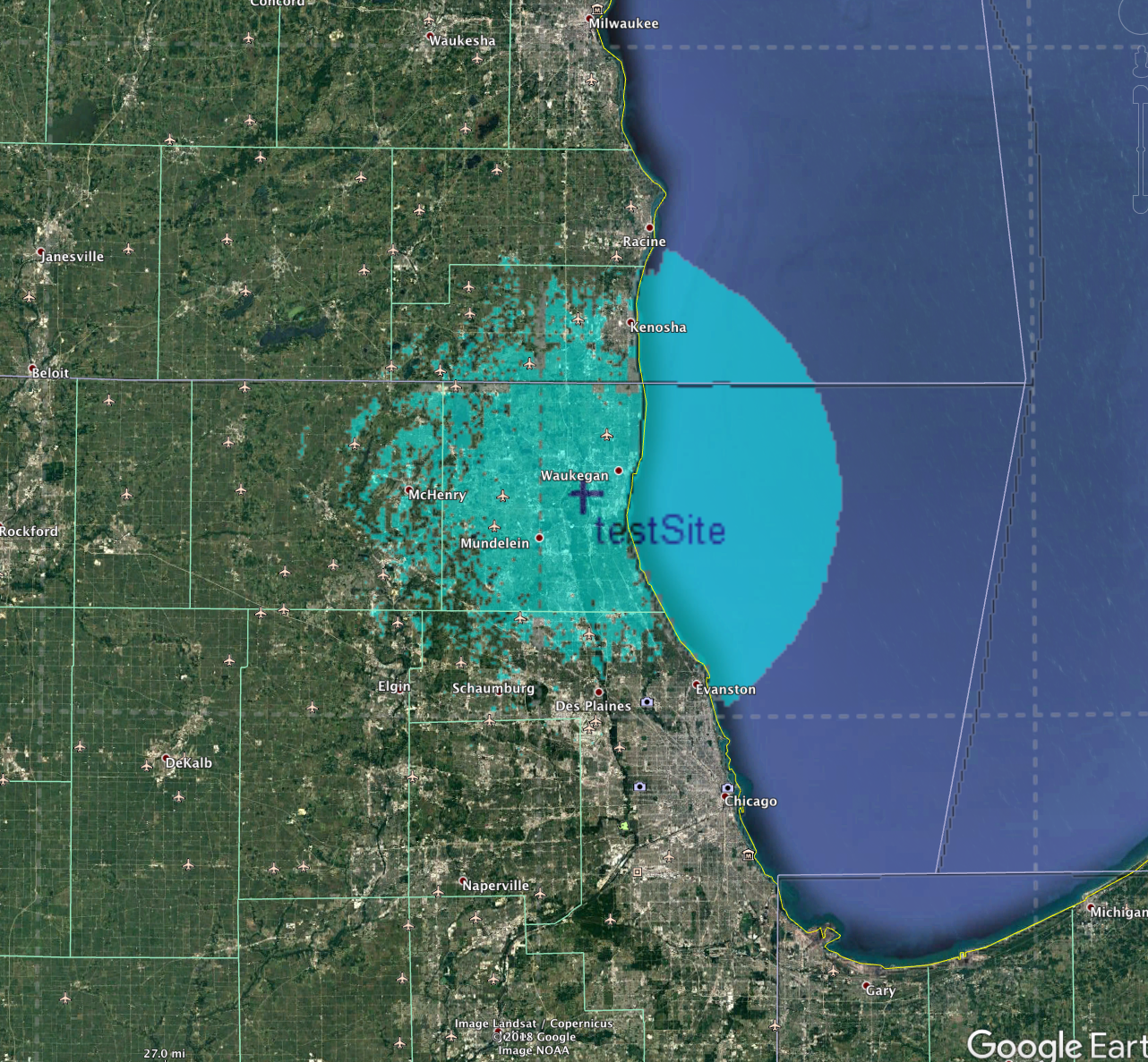
In ComStudy it also has proprietary land-cover databases which ship with it.  Much like a DEM file, this identifies the type of cover in a given area, which changes the radio propagation characteristics of that area.  We have a model with the LCF enabled and it’s much smaller as well.

Comparisons

SignalServer with PL5

This was the closest comparison, and based on the PathLoss docs, we believe PathLoss has implemented a truthful version ITM algorithm.  This would confirm the SignalServer/SPLAT! model as being correct as well, and we belive this confirms it is the case.

In the below, SignalServer is in red and the PathLoss model is in blue.

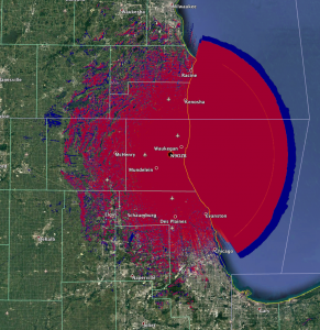
The slight variation over water (3km) and the open arc in the PathLoss model would indicate it has two ray turned on by default.  This only comes into effect over large flat reflective areas such as water.  Over land the models align 99%.

Looking at the fringe coverage we see the same tiles, just slightly offset.  This may be due to the datum used internally in PathLoss not being corrected to the WGS84 datum of our coordinates.  This would further confirm the agreement both SignalServer and PathLoss have a true ITM model implementation.

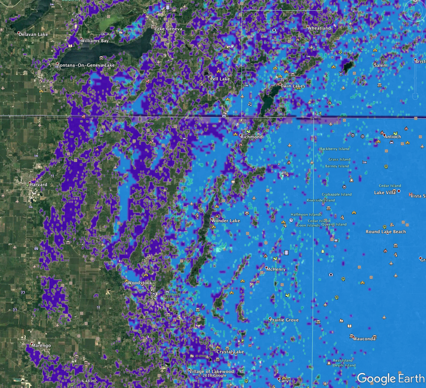
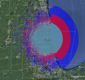
SignalServer with ComStudy

ComStudy claims to implement the same ITM model, however it doesn’t appear to be the same.  We’re not certain why this is, perhaps it’s due to some of the speedup code or just a general desire to mix the ITM with an empirical model as they can call it the ComStudy model.  ComStudy also may take into account the LCF data for land cover and we have presented that below as well.

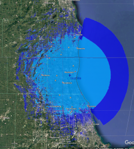
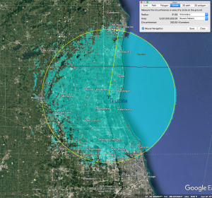
ComStudy with a 42km vs 62km radius in SignalServer.  ComStudy is the lighter blue color.

We’re not certain why it’s different, but at least in the areas that are covered ComStudy and SignalServer seem to align; looking to the north west above McHenry on the map we can see gaps between the airports and they align in both models.  This may be due to the ComStudy using a different height, correcting for antenna gain, or another issue.  What we do see is that the models do appear to use the same DEM data to determining a valley or non-coverage area.

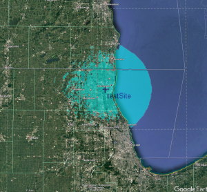
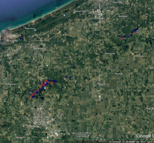
Zoomed area showing the alignment between areas in ComStudy and SignalServer.

This is the overlay of the ComStudy on Signal Server with the land cover data.  We can see this LCF data has impacted coverage to the north and south over land.  This does give some value to the theory ComStudy may be adjusting the DEM data for forested regions as suspect in the other non-LCF model, and explain some of the descripency between it and SingalServer/Pathloss.

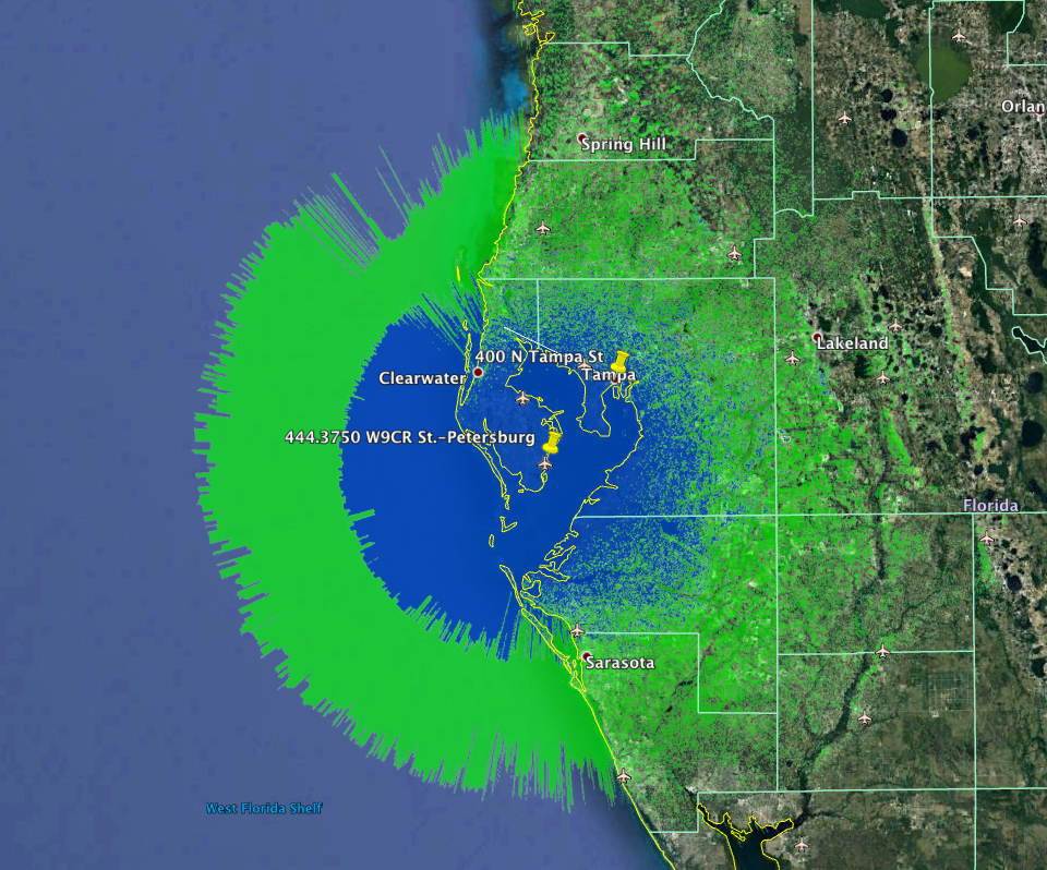
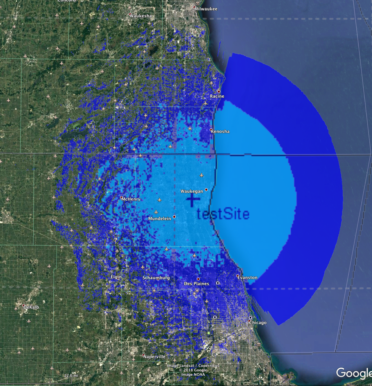
RadioMobile vs. SignalServer

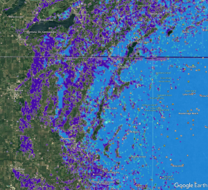
Perhaps in the most interesting study, we found RadioMobile to vastly overstate coverage compared to the other three programs.  This may be due to the primary user base of amateurs who are wowed by the enhanced coverage predictions, thus it encourages many users.  It may also be the “speed ups” done to allow RadioMobile to so fast.  Indeed RadioMobile was the fastest to produce a model of any of the programs tested.

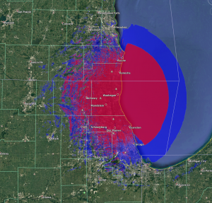
In the above we can see the overstated RadioMobile plot in blue and the SignalServer plot in red.

Here we can see the light blue of the ComStudy in the center, red of SignalServer and then the blue of RadioMobile.

We’re not certian why this is with RadioMobile, but have found ~15 dB of reduction of ERP will bring the model to align more with SignalServer and Pathloss.  This was not tested in other areas and we caution anyone using RadioMobile (or any non-Free Software) to not trust the results.  We cannot recommend using RadioMobile for any real modeling of amateur repeaters due to these issues.


Conclusions

The intent of this research was to compare and validate SignalServer’s ITM model with other popular radio propagation software models.  We found a great agreement between SignalServer and Pathloss, confirming a faithful implementation of the ITM model.  ComStudy was shown to be slightly less generous with coverage, but where the models did overlap, we found they agreed.

RadioMobile was the outlier, and was found to be greatly overstating a coverage area, and no alignment with even common areas of coverage in SignalServer.  Based on this the author cannot suggest the use of RadioMobile.


References

SignalServer 39 dBu model Keyhole Markup File
Signal Server 39dBu red KMZ 
ComStudy 2.2 with no landcover
Pathloss 5.0 Study
RadioMobile
ComStudy 2.2 with landcover

SRTM mission overview on wikipedia
Shuttle Radar Topography Mission on the JPL homepage

ITM Model homepage on the Institute for Telecommunications Sciences

FASMA Library

SignalServer – Github fork by N9OZB
SPLAT! – Homepage
RadioMobile – Homepage
ComStudy – Homepage
Pathloss
– Homepage

Join FASMA at HamCation 2018

FASMA will be present at Hamcation 2018 with a booth in the main exhibit hall.  Please come by and speak with the board; feel free to ask any questions you have.

This will be a first for either the FRC/FASMA to have a public outreach presence at the premier hamfest in the southeast.  This is a continuation of the new FRC, now FASMA, boards promise to it’s membership.


Please come out and say “hi”.

FASMA will be in both #225 in main hall

Central Florida Fairgrounds and Expo Park
4603 West Colonial Drive
Orlando, Florida 32808

February 9, 2018 | 9AM to 5PM
February 10, 2018 | 9AM to 5PM
February 11, 2018 | 9AM to 2PM

Itinerant Repeater Policy

Summary

FASMA receives many requests for low power, limited coverage repeaters for experimental, mobile, temporary “emergency” systems, neighborhood CERT teams and for just plain “fun”.  The FCC refers to such temporary operation as “Itinerant” users. Due to the number of repeaters on the air, it is difficult to find available frequencies to manage this need, due to protection contours of existing machines.  In some areas, there are no available frequencies to assign within the repeater band plan spectrum.

Our technical committee proposes the following plan to accommodate these needs in a simple, easy to understand manner.  We hope this policy will promote more experimentation in repeater systems, add to the body of experienced repeater operators within FASMA’s members and serve the public interest in times of emergency with a planned deployment guide and coordination of, portable, emergency and mobile (such as those used at Hamfests for group communications) repeaters that can add to the general usefulness of Amateur Radio systems.  Plus, we hope it allows everyone to have more fun messing around with Ham Radio gear!

Due to existing band plans and congestion, this proposal only identifies suitable frequencies on the  70 centimeter band.  Research has shown the two meter band is too congested and no standard frequency pairs are available statewide.  220/902/1.2 GHz would likely support such itinerant operation and is best the subject of future study.

There is now a plethora of inexpensive 70cm radios now on the market that can service users of Itinerant repeaters. Itinerant repeater pairs are available on a non-exclusive, first come, first served on line application environment for interested parties.

The application process is designed to help applicants learn and understand the basics of the RF parameters needed to plan a working system.  FASMA staff is available, on a volunteer, as time permits, basis, to consult with applicant’s system details, however, applicants will be required to “do the math” on their application.  Through this process, FASMA hopes to encourage learning and broaden the understanding of the details of repeater planning, service contour definition, interference potential and other facets of repeater systems and add to the available technical talent of Florida amateur radio operators as a whole.

Itinerant Repeater Proposal

These repeaters are the Amateur Radio analog to the new FCC licensed Low Power FM stations now being shoehorned into the FM broadcast band.  They are intended for short range, local, limited coverage.

Itinerant repeaters may use any appropriate modulation formats, either digital or analog. The only limitation to the modulation parameters is that any modulation used must not exceed 20 kHz for wideband or 11.7 kHz for narrowband pairs. Multiple modulation formats may be used on a single machine at any time, even concurrently.  Repeaters may be designated as analog, digital or mixed format by operators.

Itinerant repeaters can be designated by as “closed” systems for their users only. However, in keeping with FCC regulations for the Amateur Service, no form of encryption on either digital streams or analog modulation may be used.

Registration of Itinerant Repeaters is predicated under the parameters illustrated in this policy.

As in any FASMA coordination, any deviation or relocation greater than 8km distance, 5m in height or 10% transmitter power will require re-coordination.

Itinerant repeater sub band frequency pairs:

Wideband Narrowband
Pair Output Pair Output
1 441.8250 1A 441.8250
1B 441.8375
2 441.8500 2A 441.8500
2B 441.8625
3 441.8750 3A 441.8750
3B 441.8875
4 441.9000 4A 441.9000
4B 441.9125
*5 441.9250 *5A 441.9250
*5B 441.9375
6 441.9500
7 441.9625
8 441.9750
9 441.9875

All pairs MUST use a standard offset.  i.e. Receive Frequency = Output Frequency + 5.000 MHz

There are 5 pairs available for wideband (25 kHz) channel use, with 14 pairs for narrowband (12.5 kHz) only use.
Pairs 6-9 are narrow band only, with 1A-4B local option only if 6-9 are in use.

Pair 5 Wideband and 5A/B Narrowband is intended to be a truly itinerant use system.

  • The intent of this channel is for hamfest or other mobile repeaters.
  • No permanent install on this frequency is permitted.
  • Users MAY temporally deploy a system on these frequencies for no longer than 36 hours. During an emergency, this rule is waived for the duration of the emergency.
  • No registration is required for this channel; however, it is encouraged.
  • Narrowband users are encouraged to use pair 5B before 5A

Frequency Agile repeaters

This plan was engineered taking into account the performance of a typical “flat pack” duplexer.  In a UHF duplexer of this type it is common to have 100-150 kHz of usable notch depth bandwidth.  This allows a wideband repeater to use a duplexer tuned to 441.8750/446.8750 on channels 1-5 with acceptable performance.  A narrowband repeater could use a duplexer tuned to 441.9625/446.9625 on channels 5-9 with acceptable performance.  Please note this is simply an explanation for the frequency layout, any duplexer should be individually tested by a competent technician prior to use and FASMA assumes no liability caused by such use.

CTCSS Required

All pairs require CTCSS/DCS/NAC/Color Code/etc. (hereafter CTCSS) transmit and receive by all users at all times.  All users of these pairs MUST use CTCSS transmit and receive in all user radios.  Proposed CTCSS codes must be coordinated via consultation with FASMA coordinators.

System Parameters

Operational system parameters for Itinerant Repeaters must adhere to the specifications described below.  Any deviation must follow normal coordination procedures.

  • Maximum service contour for the purposes of planning co-channel assignments is 20 km (12.5mi) (assuming the maximum 15.3m HAAT (50 ft. Height Above Average Terrain).
  • No protection of service coverage past the above defined service contour description
  • Maximum Transmitter Power Output (TPO): No more than 40 watts into antenna
  • Maximum total allowed Effective Isotropic Radiated Power (ERP) in the system: 110w
  • Maximum allowable antenna gain: 6 dBd.
    This is in the range of the common Diamond X50 and its clones, which is one of the typical antennas for these applications. For better null fill “close up”, such as for CERT applications within a neighborhood, a simple unity gain ¼ ground plane is recommended due to the broader radiation pattern of these antennas.
  • Maximum antenna height to center of radiation: 15.3m (50 ft.)
    A 43-foot tower could wear a Diamond X50 at its apex to qualify. This is technically within the reach of people wanting a local repeater and enabling their deployment in most normal city/suburban areas in Florida.
  • Height above Average terrain must not exceed 60 feet out 25 miles.
    This typical of a suburban location in Florida terrain. This precludes someone living at the base of Bok Tower from applying for an Itinerant repeater system – The HAAT for this location is out of range.

Registration Requirements

Prior registration would be required and these repeaters will be listed in FASMA based repeater coordination lists and reports.  All FASMA requires for this repeater service coordination from the applicant are the following system parameters:

  • Ownership Group/Individual address, contact telephone number and email address
  • Callsign of both the trustee/owner and the repeater itself (if different)
  • GPS coordinates of the location (degrees and minutes to two decimal places)
  • Repeater equipment make, model and maximum power output
  • Feedline loss figure
  • Antenna make and model with gain figure
  • Effective Radiated Power
  • CTCSS tone choice
  • Emission designator (preferable) and/or modulation type (WBFM, NBFM, D-Star, DMR, etc.)

Any proposed change in facilities to increase repeater range would require re-coordination to a “main band” frequency, if such a frequency is available for the proposed site.  In cases where, for a given metropolitan area, a “main band” frequency becomes available, Itinerant repeater operators can request a facilities upgrade to that frequency.  Applications will be processed in accordance with normal coordination procedure.

Interference protection

Itinerant repeaters must accept interference from adjacent channel systems close to their coordinated pairs.  Itinerant repeaters operate on their frequency on a “secondary” basis and must accept any interference from other co-channel or adjacent channel users.  Itinerant repeaters shall not continuously utilize a channel via broadcast or other transmissions. Users shall restrict all transmissions to the minimum practical transmission time and must employ an efficient operating procedure designed to maximize the utilization of the spectrum.  This is analogous to the FCC FB2 station class code in the land mobile spectrum.

The only interference abatement available to Itinerant repeater operators is either antenna terrain shielding or CTCSS tone management.  Only one CTCSS tone shall be used for access to Itinerant repeaters.  Multiple CTCSS tones are not allowed. Changes to CTCSS tone must updated in the repeater’s registration in the FASMA database.

Build Out Notification

Itinerant repeater application and grant will be a fully automated service via the FASMA website.  System owners/trustee will have a maximum 60 days to report operational status (build out).  If operational status is not reported to FASMA after 60 days, the repeater registration will be revoked and the frequency will be available for reassignment.  If any Itinerant system is found to be off the air, the repeater registration will be revoked.

If the operator ceases operation for any reason, the operator shall notify FASMA.

Notes

This is a proposed policy was open for public comment before adoption.   Our policy making is candid process; we continually seek input and new ideas from the community.   We encourage any amateurs wishing to effect change in the operation of coordination in Florida to submit a proposal or comment on existing proposals. We request all comments to rt@fasma.org.

This policy has been enforce since 2018 without issue.  It is adopted for use of all amateurs in Florida.